
Von der Deutschen Forschungsgemeinschaft (DFG) im Rahmen der Großgeräteinitiative „Messsysteme für ultrahohe Datenraten für Kommunikationstechniken der Zukunft“ gefördert.
Crosslink offers a novel ultra-wideband millimeter-wave to submillimeter-wave instrumentation setup for the characterization of transceivers and multiplexers and their functional building blocks dedicated to 6G Terahertz communication. The measurement system comprises a wideband (64 GHz) arbitrary waveform generator, wideband frequency up- and down-converters into the extended WR10 (70-110 GHz) and WR3.4 (220-325 GHz) bands, coupled to a novel directional coupler which allows for the calibration of wideband complex modulated signal in terms of vectorial signal distortion in the RF domain, down-converter modules, a vectorial network analyser with to option of spectrum analysis in the frequency domain, and a wideband (100 GHz) sub-sampling oscilloscope for the time domain. Using predistortion of the baseband input signal, the calibration plane for complex
modulated communication signals can be shifted to the input and to the output of a device-under-test such as an amplifier. CrossLink enables the simultaneous and in-situ measurement of 6G components in the time and in the frequency domain, as well as the investigation of frequency-division multiplexing techniques inline with the IEEE802.15.3d frequency standard for THz communication. In first measurement, the input and output-
related calibration of solid-state power amplifier modules at a center frequency of 77.5 GHz for QPSK and 256-QAM modulation with 1 and 4 GBd symbol rates as well as at 300 GHz for QPSK and 64-QAM modulation with 16 GBd and 1.6 GBd symbol rates, respectively. The in-situ calibration in the RF domain enabled by CrossLink reduces the error-vector-magnitude by an order of magnitude.
6G component characterization solution
Three key novelties are at the heart of the novel measurement setup:
- The cascade of a wideband up-converting mixer (CCU) with a directional coupler in the custom frequency extension unit (VCA) in the respective waveguide bands.
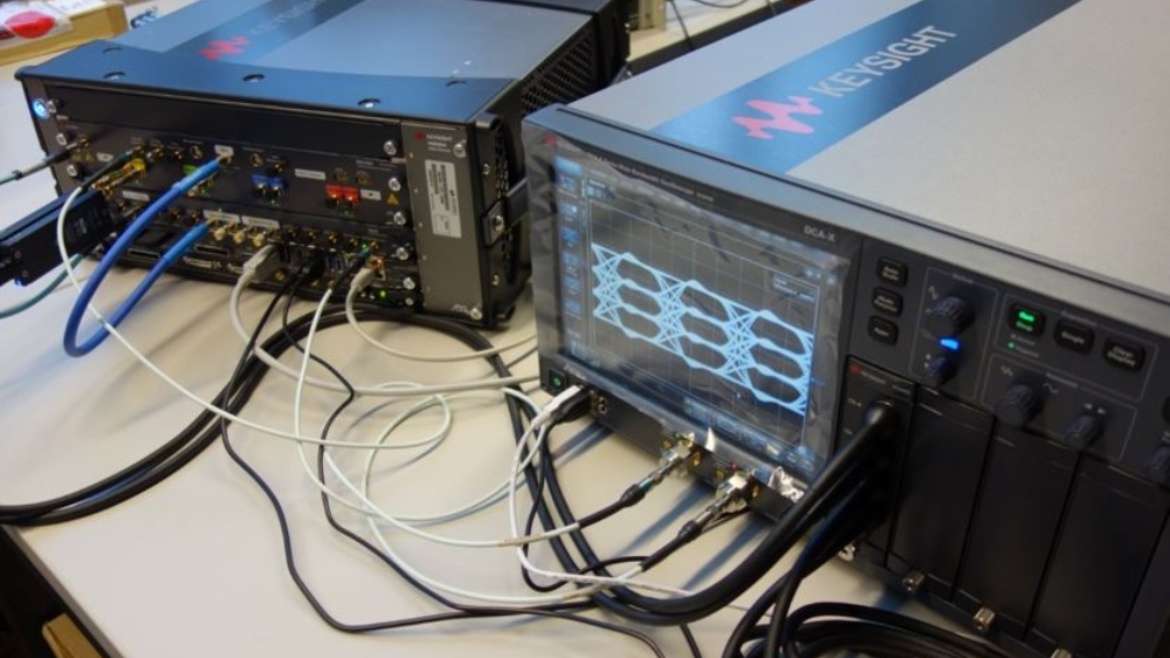
- The combination of synchronous signal analysis in the time and frequency domain.
- Repetitive test signals to enable vector averaging, wideband stitching, noise floor reduction.
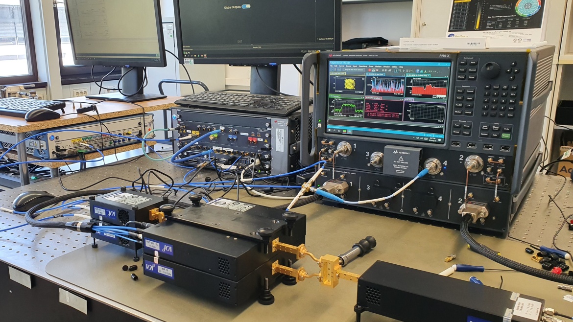
Fig. 1 shows a photograph of the measurement setup, whose functional components are depicted in the block diagram of Fig. 2.
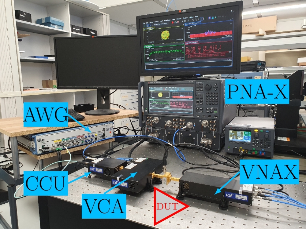
The CCU up-converts the wideband modulated signals centered at a low intermediate frequency which are generated in an arbitrary waveform generator (AWG). In our setup, the AWG is capable of using up to 43 GHz of analog bandwidth. In doing so, the CCU distorts the signal and degrades the EVM of the excitation signal, while up-converting the signal to an RF frequency band of interest. The source calibration can be done in two ways: inline and offline. For inline calibration, which can be performed without interfering with the DUT connection, the VCA is used to down-convert and analyse the input signal injected into the DUT by the time domain signal sink, and a predistortion can be applied to the AWG in order to calibrate the signal for minimum EVM at the CCU RF output, i.e. the DUT input plane. This inline calibration also accounts for the effects of impedance mismatch between CCU output and DUT input.

Projektförderung - DFG Großgeräteinitiative
2019 - Messsysteme für ultrahohe Datenraten für Kommunikationstechniken der Zukunft
Die DFG fördert vier Messplattformen zur Erforschung photonischer, Millimeterwellen- und THz-Kommunikationssysteme bei der Übertragung massiv anwachsender Datenmengen mit immer höheren Datenraten. Die ständig steigende Nachfrage nach drahtloser Kommunikation mit ultrahoher Datenrate erfordert die Erschließung neuer Frequenzbänder im elektromagnetischen Spektrum. Die leistungsfähigen Plattformen ermöglichen die messtechnische Charakterisierung solcher Systeme und Subsysteme für ultrahohe Übertragungsraten entlang der gesamten Übertragungskette und erlauben die synchrone Zeit- und Frequenzbereichsanalyse von ultra-breitbandigen Kommunikationskanälen.
Die Einreichung der Universität Stuttgart (ILH und INT) wurde bewilligt und wird gefördert unter der Projektnummer: 434501119
Presse
- DFG Pressemitteilung
Pressemitteilung Nr. 63 | 9. Dezember 2019 - Messplattform für Kommunikationstechniken der Zukunft
Universität Stuttgart - Hochschulkommunikation
Publikationen
2023
- 1. B. Schoch, D. Wrana, A. Tessmann, and I. Kallfass, “Wideband Cross-Domain Characterization of a W-band Amplifier MMIC,” in 2023 53rd European Microwave Conference (EuMC), in 2023 53rd European Microwave Conference (EuMC). Sep. 2023, pp. 770–773. doi: 10.23919/EuMC58039.2023.10290485.
- 2. I. Kallfass et al., “Instrumentation for the Time and Frequency Domain Characterization of Terahertz Communication Transceivers and their Building Blocks,” in 2023 IEEE/MTT-S International Microwave Symposium - IMS 2023, in 2023 IEEE/MTT-S International Microwave Symposium - IMS 2023. Jun. 2023, pp. 1030–1033. doi: 10.1109/IMS37964.2023.10188006.
Kooperationspartner

Keysight Technologies
Virginia Diodes, Inc.
CrossLink - News

Benjamin Schoch
M.Sc.Group Leader High Frequency Electronics / Research Assistant